Front Sensors // 01.19.2013
|
Two parts to this: mount the sensors, then route the cables. Mounting the sensors was one of the easiest pieces of the entire install, but the hardest to decide on. I gathered all the info I could from as many sources as I could find. Some of the die-hard laser jammer folks would talk you into mounting a bracket in front of your headlights as proper protection (ah, yeah...), and many installers take form clearly over function. My goal was for the system to be as efficient as possible, without seriously encroaching on it taking away from the look of the rest of the car.
|
Install Details:
|
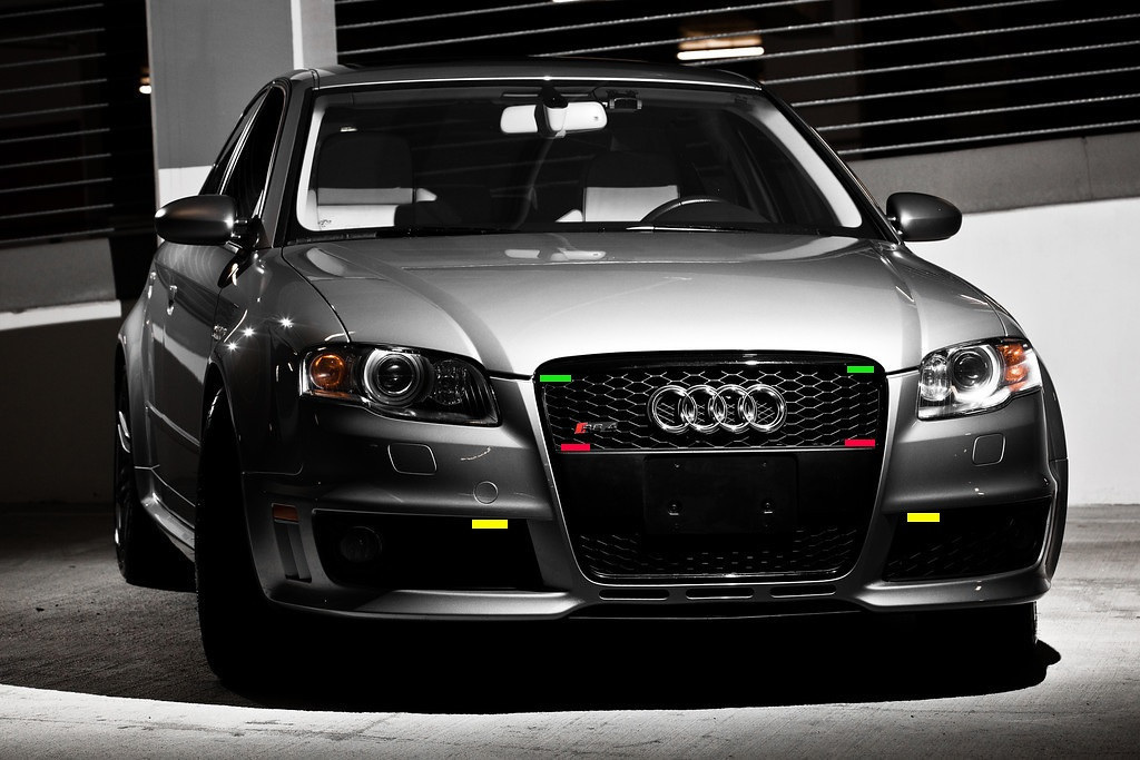
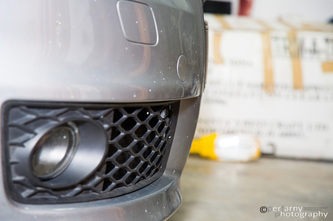
Then I poked around QW and AZ to see what other people had done, and also went to my trusted installers at Benchmark Motoring and talked to them. Some have installed as low as the splitter in the middle and reporting zero issues i.e. many saves and no misses. Benchmark opinion was 'as long as it has a clear view, you should be fine'. Given all of the above, I decided to meet somewhere in the middle and install in the fog light grill area, i.e. the yellow areas above.
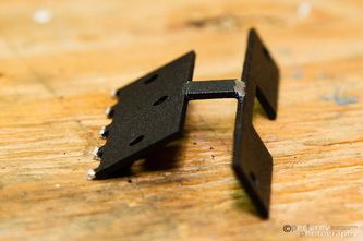
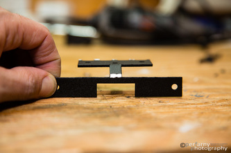
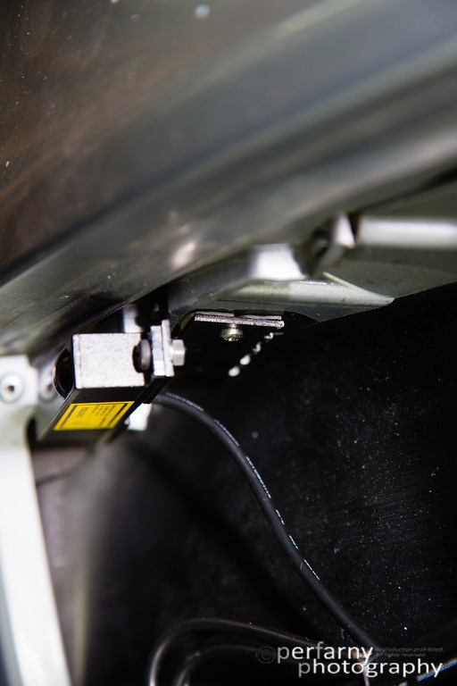
I spent a lot of time removing the grill and holding the sensors in various positions knowing they needed to be level and also straight forward (not toed in our out), and trying to determine where and how much I needed to cut out of the grill's to make it happen. It became clear quickly that I needed to use one of the supplied brackets vs. just taping the sensor to the car directly. So, I took the straight brackets they supply, bent off excess on one end, and adjusted the rest for best fit by putting in my vice grip. The left side below is what mounts to the car, the right is what the sensor gets mounted to. This way, the sensor will be level, and as high up on the fog light grill as possible:
I spent a lot of time removing the grill and holding the sensors in various positions knowing they needed to be level and also straight forward (not toed in our out), and trying to determine where and how much I needed to cut out of the grill's to make it happen. It became clear quickly that I needed to use one of the supplied brackets vs. just taping the sensor to the car directly. So, I took the straight brackets they supply, bent off excess on one end, and adjusted the rest for best fit by putting in my vice grip. The left side below is what mounts to the car, the right is what the sensor gets mounted to. This way, the sensor will be level, and as high up on the fog light grill as possible:
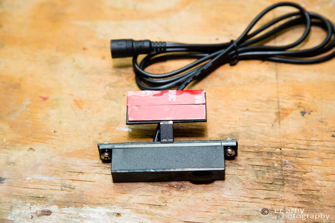
Mount the sensor and apply the 3M tape. BTW - the screws that come with the LI are silver; I spray painted them black before mounting.
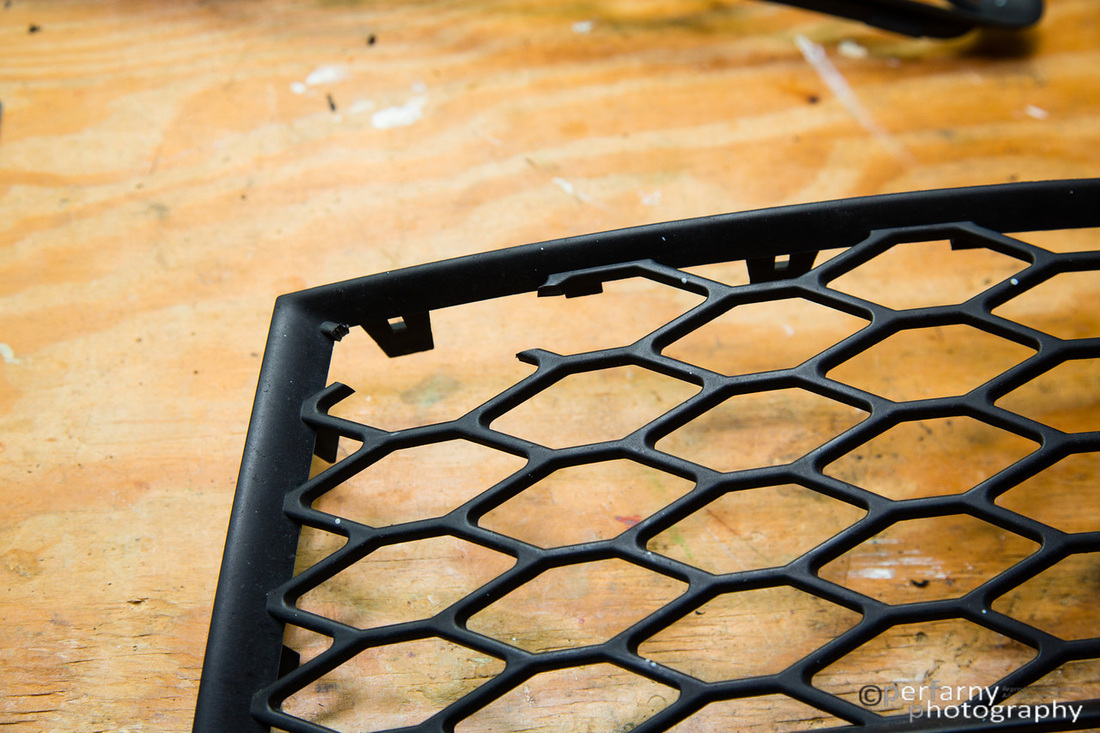
The fog light grills after the dremel went to work:
|
In order to find the exact spot in the first place, put the sensor on the inside of the now cut fog light grill, put the grill into place and position the sensor as best as you can with your hands making sure it's level, and that it faces straight forward. Doing your best hand acrobatics, get a thin point Sharpie through the fog light mesh (at least the front half) and draw a line to mark where exactly you should mount the bracket. Once you feel good about the exact spot, remove the grill and apply the tape/sensor. Since a good chunck of the bracket is not secured directly to the body, I chose to also screw one of the supplied screws into the body...it's not going anywhere now.
|
I did some fine filing after the above, particularly in the upper left corner, just to make it a bit more finished.
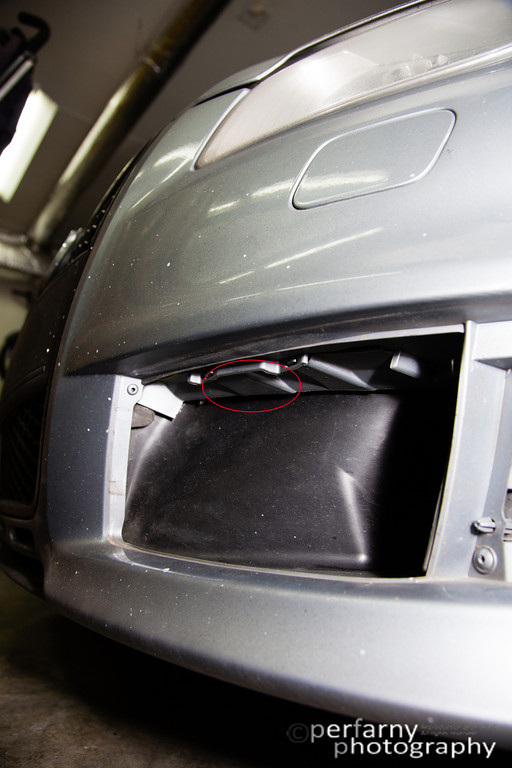
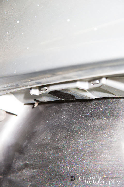
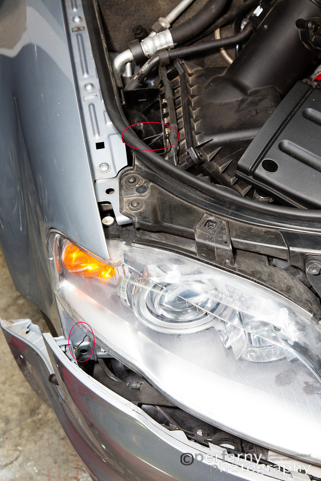
As far as mounting the sensors on the car, the spot I mounted to is circled below. Cleaned it off nice before doing anything (the rest of the car quite dirty, though at the time :/). A couple of notes on that: that area (the piece that extends downward a bit) is not as wide as the mounting bracket itself (leaves about half of it actually not in direct contact with the body), and also, the 3M molding tape will take off the paint from the plastic very easily. I stuck a sensor on, and wanted to adjust a bit, and boom...paint off :( At this point, use the supplied bubble level and start making sure it's level on all axes. The mounting bracket is maleable enough to allow you to adjust it fairly extensively. Once you think you have it pretty well set, reinstall the grill. I found that with both sides, I envitably had to cut a bit more out of the grill as the sensor hung down further than I expected and would rest on the lower part of the grill cut out, once again not making it level. Not a big deal; just know you might need to do some of this. Even if you got it perfect on the first try, weave the supplied bubble level to the inside of the grill, and re-check that everything is still level.
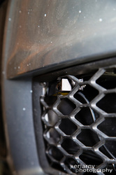
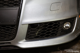
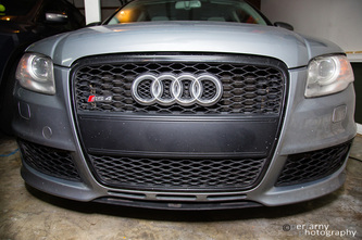
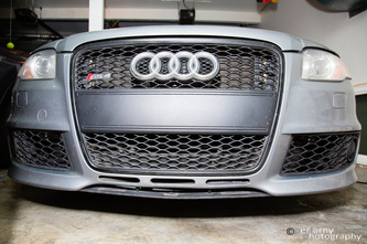
Finished pics below (click for hi-res), with the sensors hardly visible. |
Now, just need to take the bumper off to properly route the cables....
Cable Routing
With the sensors mounted, I needed to route the cables up into the engine bay, to the ECU, and inside to the LI CPU. I used the straight forward DIY on bumper removal. The key to make it easy: get the right tools. To me, the most important was the flexible extension to enable the removal of the two 10mm nuts from inside the bumper. On that note, I'd like to formally curse the last person who reinstalled this bumper for using an 11mm nut on the lower drivers side. Wasted about 30 minutes trying to figure out what the hell was going until I figured that out.
Note that I didn't actually remove the entire bumper, but let it hang loosely. It gave me plenty of room to work the cabling, and saved me from trying to reinstall all by myself.
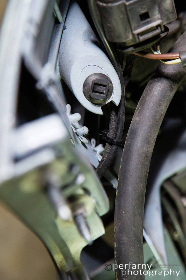
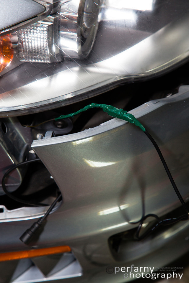
Coming from the bottom up, I zip tied to the fog light wiring leading upwards.
Note that I didn't actually remove the entire bumper, but let it hang loosely. It gave me plenty of room to work the cabling, and saved me from trying to reinstall all by myself.
Coming from the bottom up, I zip tied to the fog light wiring leading upwards.
Followed that up to about the middle (in height) of the bumper and added one more zip tie.
This now was at the right height to have the cable go across and on its way into the engine bay.
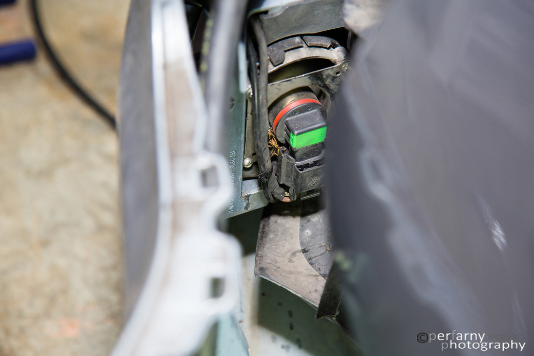
In the above, you see the lower of the two mounting points where the bumper attaches (i.e. the pain in the ass nuts to remove from inside behind the wheel liner. There is plenty of free (and safe) space to put the connectors right behind this. I didn't take a picture here, but if you check out the rear sensor install section, you can see that the LI receivers come with a short run of cabling attached (3 feet?) and then an additional 6' of cabling that connects to the receiver end via a DIN connector, and to the CPU via an RJ45 connector. I connected the two ends here, wrapped a bit of electrical tape around them to make sure they don't separate (but they're very solid connections already) and worked on where to go next with the cabling.
To figure out which was the best way to go up, I used the old coat hanger trick. Stuck the coat hanger in from above from a location that looked promising, and checked if I could see it come out the other end. Below, a shot of that for the passenger side (both ends of the coat hanger circled in red).
To figure out which was the best way to go up, I used the old coat hanger trick. Stuck the coat hanger in from above from a location that looked promising, and checked if I could see it come out the other end. Below, a shot of that for the passenger side (both ends of the coat hanger circled in red).
Once through, attached the end of the RJ45 connector to a zip tie, and then to the coat hanger, and pulled it on through.
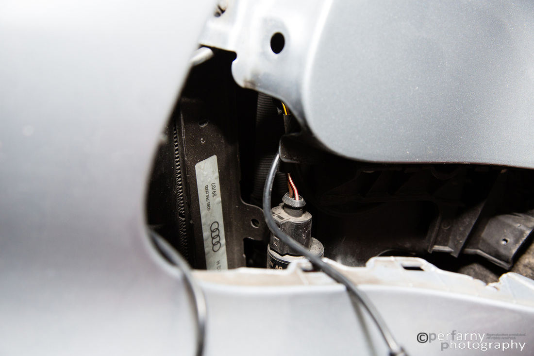
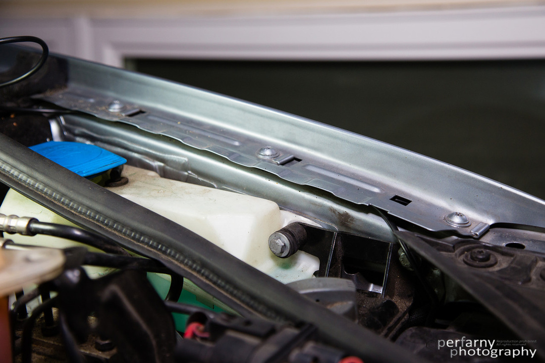
With the cable up into the engine bay, I tucked it in behind the weather sealing on both sides. Here you see the drivers side.
At this point, you can reattach the bumper. The only advice I'll give here that hasn't already been covered in the various DIY's is: when securing those 10mm nuts, on whichever side is the last one that you do loosely place both nuts on before tightening either one. This allows for the angle not to be too extreme. I battled a while with trying to get the last one threaded correctly even with my flex extension. Got in in 30 seconds once I figured out the above approach.
Focusing on the drivers side first, I needed to get the cabling into the ECU box and down into the cabin from there. First time removing the ECU cover for me on this car, and was thrilled to find out it's even more of a pain in the ass than on the B5 (it's all about that last screw in the corner closest to driver and fender!). I followed presribed process, which includes removing both wiper arms and the cowling. Well, I did it halfway: removed nuts from both arms, got passenger off, but not drivers, so proceeded to thread torx on swivel joint into the area and remove the screw, then squeeze out cover. Kinda' painful, and I'm surprised I didn't snap the cowling, but in the end: it worked.
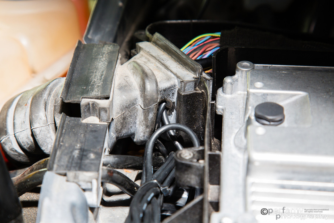
Slit a bit into the rubber grommet leading into the ECU, and used the still taped zip tie to connector to easily pass it into the ECU compartment. You see both cables already threaded through here.
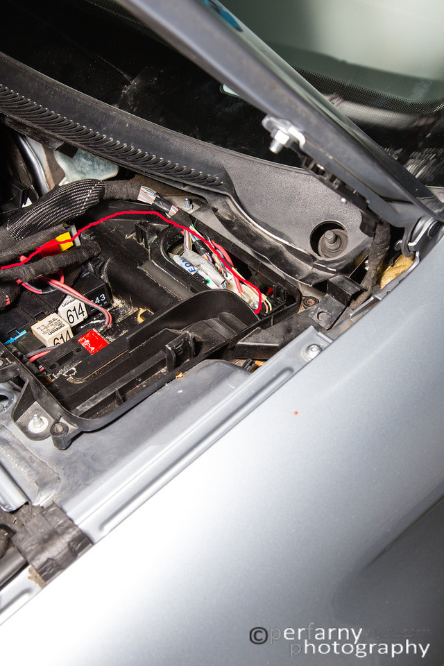
Inside the ECU compartment, I routed the cables as per the red line below. That leads them into the cabin, very close to where they need to go (fuse box is where CPU is mounted).
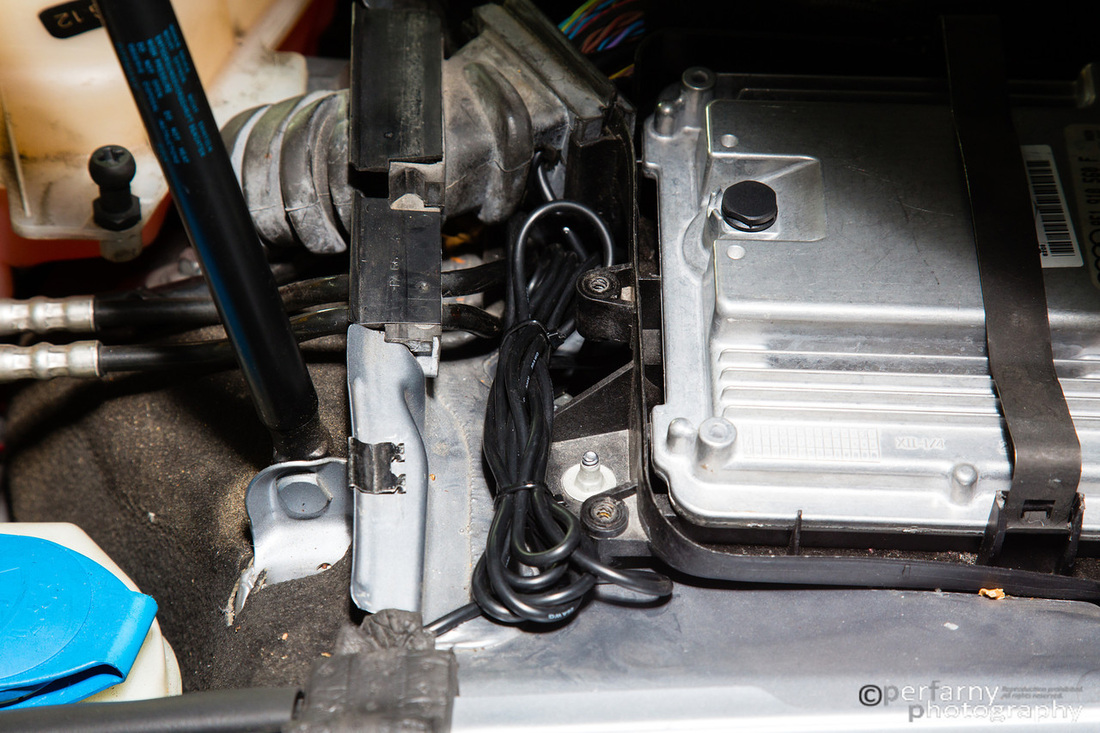
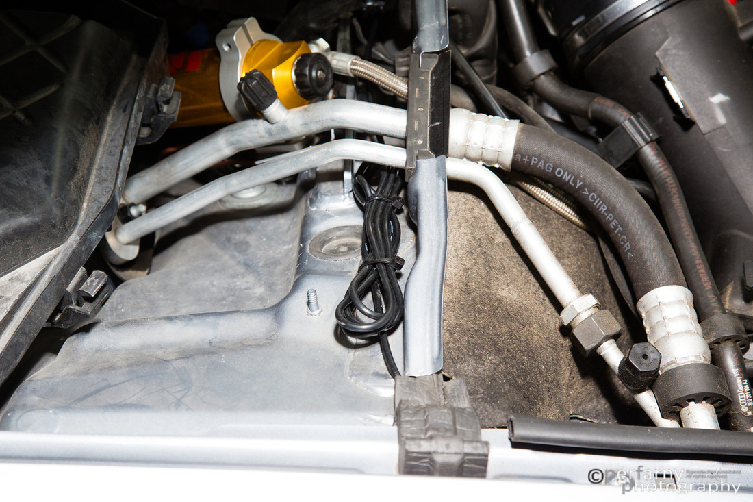
I knew I had a lost of excess cabling, and also knew I didn't want to stash it underneath the dash as with everything else I have going on underneath there it was starting to get messy (V1 hardwire, LI CPU and cables, P3cars gauge). So, I switched to inside the cabin, took off the knee bolster, and pulled through enough cabling so that I could easily remove CPU in the future without needing to tug. That still left plenty of extra which I secured outside the ECU compartment for the drivers side: (left) and passenger side (right).
No pics of getting from the inside to the CPU location, but trust me, it's 12 inches away once you're inside...very easy.
That's it, that's all. I need to find someone in the area to test the setup with now. Very happy with how it turned out overall.
That's it, that's all. I need to find someone in the area to test the setup with now. Very happy with how it turned out overall.
